Note 15: This is the capacitance needed to form an LC resonant tank.
#Air core inductor calculator mm driver#
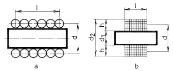
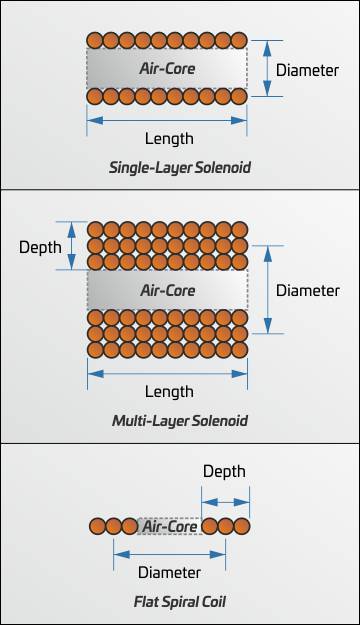
Note higher voltage is need for AC waveform using the an amplifier driver such as the TS250, because resistance increase rapidly at higher frequency. As resistance is increase at hot, higher voltage is needed. Note DC resistance is calculated at room temperature. Note 14: This is the minimum voltage needed to drive the coil. It is calculated using inductance, frequency, and resistance. Note 12: Coil inductance in micro- Henry (uH). Resistance is further increase at higher temperature. Note 9: Calculated magnetic field at a distance from the coil center. A practical compact factor range is 0.88 to 1.0. This is the most tightly wound with no space wasted. However, practical wounding is shown in Figure 4. If the coil is wound such that the distance between two copper layers is equal to the diameter (Figure 3), the compact factor is equal 1.0. Note 8: Enter the coil winding density compact factor. Note 7: Enter the core relative permeability constant, k. Another example, a distance of 25mm means the magnetic field is calculated 10mm outside of the coil (30mm/2+10mm = 25mm). For example, if the coil bobbin width is 30mm, a distance of 15mm is at the coil edge. Enter zero for the magnetic at the center of the coil/solenoid. Note 6: The calculated magnetic at a distance from the center of the coil, see Figure 2.

For DC, just leave the default 1kHz and use the DC parameters calculated below. Note 5: Enter the solenoid/coil operation frequency (sinewave). If the current is AC, this is the peak current. Note 3: Enter the number of turns in the coil or solenoid.

Use Table 1 to enter the bare copper wire diameter. This diameter is used to calculate the resistance more accurately. Table 2: Copper wire diameter WITHOUT coated insulation. Use Table 1 to enter the copper wire diameter. Table 1: Copper wire diameter with coated insulation. The coil width is same as the bobbin inner width. Note 2: Enter the length of the solenoid or coil. Copper inner radius must be larger than bobbin inner radius. Note the copper inner radius is not same as the bobbin inner radius. So far, the feedback shows that theory=practice, generally to less than 0.2%.Note1 : Coil copper inner radius from the center to the first layer of copper.

I've actively sought feedback from people who have the facilities to measure actual values accurately, and compare them to the calculated values. I became obsessed, did some research, and found out that there were far more accurate formulae than those currently available on the web, but it appeared that those people who'd created the various calculators, were far more interested in creating calculators than actually providing something that gave accurate results. (We all have our foibles.) Several years ago, I was trying to do some calculations for some coils that didn't fit the usual coil geometry, and the numbers refused to work out. I confess to being a bit of an inductance evangelist. **broken link removed** which uses an empirical formula that I developed (error < 20 ppM), but doesn't include corrections for conductor size, so there is some loss of accuracy, but still not too bad.
#Air core inductor calculator mm plus#
(my own calculator, so I'll admit to being biased), which uses the theoretically exact elliptic integral formula, plus conductor size corrections.ģ.

which uses Lundin's very accurate empirical formula (error < 4 ppM), and includes corrections for conductor size.Ģ. Sadly, virtually everything I've found on the web is Wheeler's long coil formula.


 0 kommentar(er)
